Digital Systems Lab
Four labs in Verilog on one FPGA board, each building on the last: a display driver, a serial link, video out, and an accelerometer that steers a bouncing logo.
9Course grade
Accelerometer over SPI
Tilt-controlled sprite

What it is
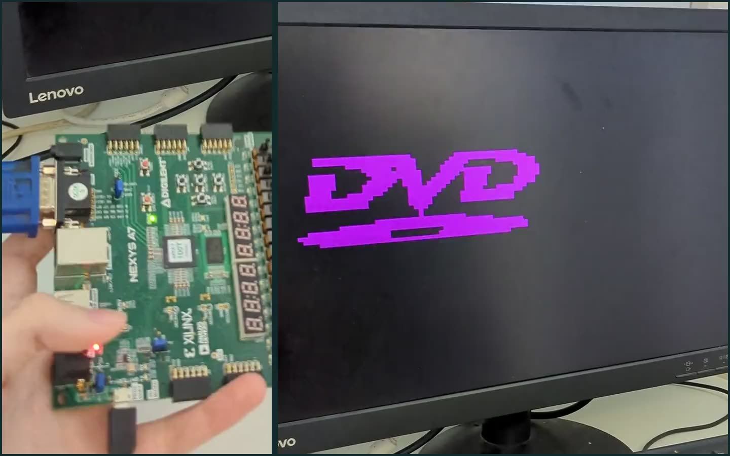
The last lab: reading the board’s ADXL362 accelerometer over SPI in Verilog, averaging its readings and sending them over the UART from the second lab as text. Then, on my own initiative, I connected it to the bouncing logo from the third lab, so tilting the board moves the logo on screen. That wasn’t part of the lab, not even as an optional extra.
Numbers as text
The readings are binary, but a terminal shows text. A converter finds the sign, then turns the number into decimal digits with the double dabble method, shifting and adding one step at a time, and adds the code of the character 0 to each digit. Its testbench found two bugs: the digits weren’t cleared between conversions, and one step ran once too often, adding 3 to digits that didn’t need it.
SPI
SPI sends and receives one bit per tick of a clock the master drives. Ours runs at 5 MHz, made by the board’s clock manager, and a counter on the fast clock tracks where in each slow tick it is, so the state machine knows when to read the incoming bit and when to change the outgoing one.
On top of it, one module sends the accelerometer its setup commands and another reads its X, Y and Z values.
Tilt to move
The accelerometer’s readings drive the logo’s position, in place of the steady motion it had before. The same work later became DVD Logo FPGA, with HDMI output, its own board and tilt, automatic and button modes.
Code
always @(current_state or enable or sclk_counter or bit_counter) begin
    case (current_state)
        IDLE: next_state = (enable && sclk_counter == SHIFT_ON) ? LOAD : IDLE;
        LOAD: next_state = (sclk_counter == SAMPLE_ON) ? SAMPLE : LOAD;
        SAMPLE: next_state = (bit_counter == 3'd7) ? COPY_RECEIVED : SAMPLE_WAIT;
        SAMPLE_WAIT: next_state = (sclk_counter == SHIFT_ON) ? SHIFT : SAMPLE_WAIT;
        SHIFT: next_state = SHIFT_WAIT;
        SHIFT_WAIT: next_state = (sclk_counter == SAMPLE_ON) ? SAMPLE : SHIFT_WAIT;
        COPY_RECEIVED: next_state = DONE;
        DONE: begin
            if (enable && sclk_counter == SHIFT_ON) begin // Continue the next transmission if enable is high
                next_state = LOAD;
            end else if (sclk_counter == DISABLE_ON) begin // End communication if enable is low and there no time left to start a new transmission
                next_state = IDLE;
            end else begin
                next_state = DONE;
            end
        end
        default: next_state = IDLE;
    endcase
endVGA controller
Video out from BRAM
What it is
A VGA video output in Verilog: a picture stored in the FPGA’s own memory, sent to a monitor at 640×480. As an optional part I added a DVD logo that bounces around the screen, the start of DVD Logo FPGA.
A picture in block RAM
The board’s block RAM is small, so the picture is 128×96 with one bit per colour, kept in three memories, one each for red, green and blue. A Python script turns an image into their starting contents. Every stored pixel is drawn five times across and five times down, filling 640×480.
Timing a frame
A monitor expects each line and each frame in fixed parts: a sync pulse, a pause, the visible pixels, and another pause. Both the horizontal and the vertical timing come from one state machine, written once with the number of cycles of each part as parameters. Its clock is 25 MHz, made from the board’s clock.
The memory takes one cycle to answer, and returns 16 pixels at a time, so the pixel controller asks for the next 16 one cycle before it needs them.
On the board
The picture showed on the first try on a real monitor, without flicker or misplaced pixels.
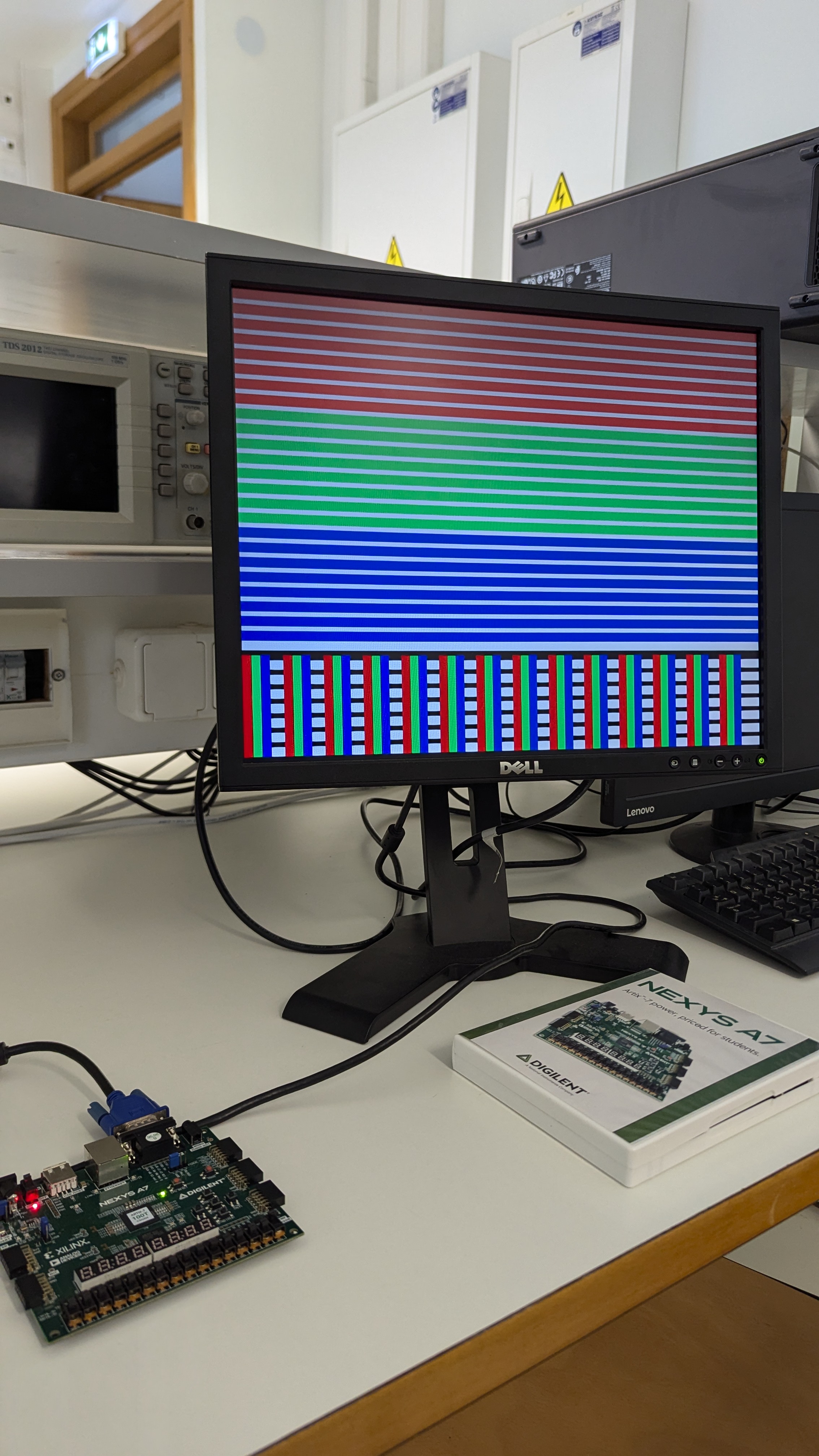
A bouncing logo
The logo lives in a block RAM of its own. Between two frames, while the monitor shows nothing, there is time to copy the whole picture again, so the logo is redrawn at its new place then and never shows half-moved. Another module moves it diagonally at a steady speed and turns it around at the edges, though in this version the bounce didn’t always land right; DVD Logo FPGA fixes it.
Code
always @(current_address or hpixel_upscale_counter) begin
    if (current_address[3:0] == 4'b1111 && hpixel_upscale_counter == UPSCALE_CYCLES) begin
        vram_address = current_address + 1'b1;
    end else begin
        vram_address = current_address;
    end
end

always @(rgb_enabled or vram_red or vram_green or vram_blue or current_address) begin
    if (!rgb_enabled) begin
        r = 1'b0;
        g = 1'b0;
        b = 1'b0;
    end else begin
        r = vram_red[current_address[3:0]];
        g = vram_green[current_address[3:0]];
        b = vram_blue[current_address[3:0]];
    end
endUART
Serial link in Verilog
What it is
A UART, the simple serial link behind most debug ports, built in Verilog: a transmitter, a receiver that catches transmission errors, and a controller that sends a set of test messages from one to the other.
Eight speeds
Both sides must agree on a speed in advance, the baud rate: eight are built in, from 300 to 115,200 bits per second, chosen with three switches. The receiver looks at the line 16 times per bit, so a counter on the 100 MHz clock pulses 16 times per bit. Rounding the count to whole cycles puts every rate within 0.47% of its exact value.
Sending
The transmitter is a state machine with a state per bit: a start bit, eight data bits, a parity bit that is all the data bits combined with XOR, and a stop bit. It reports when it is busy, so the controller knows when it can send the next byte.
Receiving, and catching errors
The receiver waits for a start bit, then reads each bit in the middle of its time on the line, when it is most likely to be steady. It catches two kinds of error. A parity error: the parity bit doesn’t match the data. A framing error: the line changes in the middle of a bit, which happens when the two sides run at different speeds.
Each error is a state of its own, held until the receiver is switched off and on again. A first version kept the errors in extra flip-flops; making them states was simpler and used three fewer.
Separate testbenches sent a wrong parity bit, used the wrong speed on purpose, and sent clean messages.
On the board
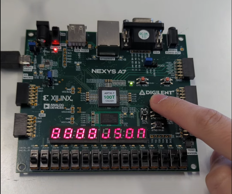
The controller sends four stored bytes, one per button press, and the receiver stores them. As an optional part, the received bytes go to the seven-segment driver from the first lab, so every press shows the next message on the display. Switches choose the speed and turn each side on or off.
Code
module baud_controller(input clk, input reset, input enable, input [2:0] baud_select, output wire enable_sample);
    reg [14:0] counter;
    reg [14:0] max_counter;
    parameter max_0 = 15'd20_833; //sfalma 1/3
    parameter max_1 = 15'd5_208; //sfalma 1/3
    parameter max_2 = 15'd1_302; //sfalma .08333...
    parameter max_3 = 15'd651; //sfalma .04166666...
    parameter max_4 = 15'd326; //sfalma -.479166...
    parameter max_5 = 15'd163; //sfalma -.23958333...
    parameter max_6 = 15'd109; //sfalma -.493055...
    parameter max_7 = 15'd54; //sfalma .25347222...

assign enable_sample = max_counter == counter;Seven-segment display
Four-digit display driver
What it is
The first lab: driving the Nexys A7 board’s four seven-segment digits in Verilog to show a fixed message, then a message that scrolls, first one step per button press and then on its own.
One digit at a time
The four digits share their segment lines, so only one can show a character at any moment. A counter cycles through them faster than the eye can see, setting the segments for one digit and switching that digit on, then the next.
The decoder turns a 6-bit character into the segments to light: the whole English alphabet, the digits 0 to 9 and a space. A testbench checked every character, and printed each one as it would look on a display, which caught a few wrong bits.
What only the board showed
The simulation looked right, but on the board the digits showed faint copies of other characters, known as ghosting: a digit was switched on while the segments were still changing. The fix switches a digit on one step after its segments are set, and off one step before they change.
Buttons
A button bounces: one press looks like many. Every button goes through a synchroniser and a debouncer, which waits for the signal to stay steady before passing it on. On the board the first debouncer’s counter was too short to work reliably; a wider counter fixed it.
The message lives in a small memory, and the button moves the four-character window along it one step per press; the last version moves it on a timer instead.
Code
module AnodeDecoder(input [3:0] counter, output reg an0, output reg an1, output reg an2, output reg an3);
    parameter AN0_OFF = 4'b0010;
    parameter AN1_OFF = 4'b0110;
    parameter AN2_OFF = 4'b1010;
    parameter AN3_OFF = 4'b1110;

    always @(counter) begin
        case (counter)
            AN0_OFF: begin
                an0 = 1'b0;
                an1 = 1'b1;
                an2 = 1'b1;
                an3 = 1'b1;
            end
            AN1_OFF: begin
                an0 = 1'b1;
                an1 = 1'b0;
                an2 = 1'b1;
                an3 = 1'b1;
endWhat came next
DVD Logo FPGA
A hardware DVD logo you steer by tilting the boardStarted as an optional extra in a lab, then ported to HDMI on the Smart Zynq SL. It is the second demo in the Live FPGA Lab.Tools
What this course's projects were built with. Pick one to see where else I used it.